PPP Ring Network: IPv4/IPv6 Static Routing and Loop Analysis
Lab Instructions
- Configure a 5-router ring topology with PPP serial links
- Implement IPv4 and IPv6 static routing for full connectivity
- Analyze routing loop behavior with default routes
The lab was designed in GNS3, using Cisco 3725 routers with WIC-2T cards.
Note: This lab was designed by Remi LEHN, Polytech Nantes - Network Engineering Course.
Topology
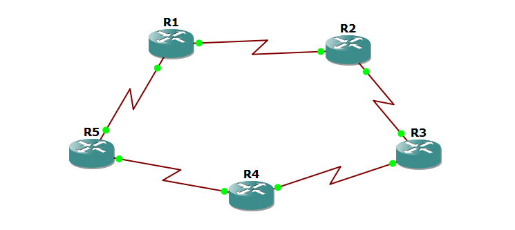
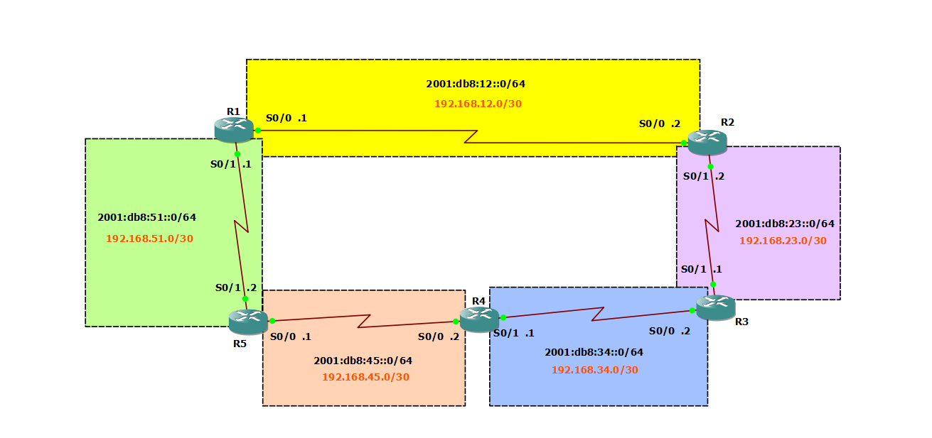
Five Cisco 3725 routers connected in a ring topology. All links use PPP encapsulation on serial interfaces.
Part 1: IPv6 Configuration
Layer 2 and Layer 3 Verification
Configure the R1-R2 link with IPv6 addressing:
R1 Serial0/0
1
2
3
4
interface Serial0/0
 encapsulation ppp
 ipv6 address 2001:db8:12::1/64
 no shutdown
R2 Serial0/0
1
2
3
4
interface Serial0/0
 encapsulation ppp
 ipv6 address 2001:db8:12::2/64
 no shutdown
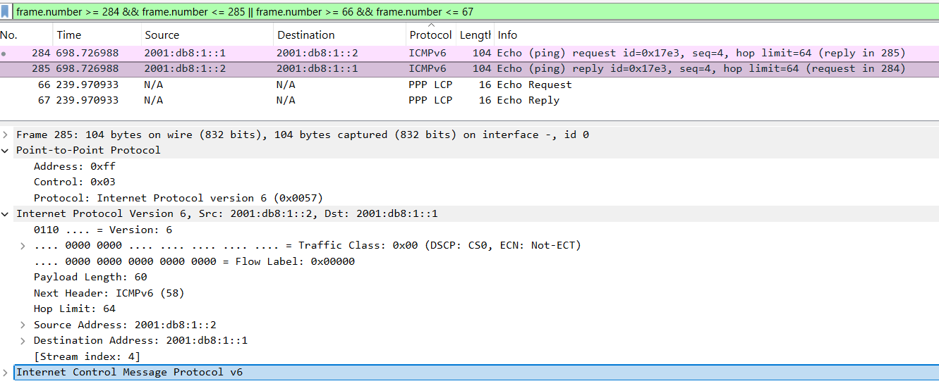
Test connectivity:
1
R1# ping 2001:db8:12::2
Wireshark capture shows:
- PPP frames at Layer 2
- ICMPv6 Echo Request and Reply at Layer 3
IPv6 Addressing Plan
| Link | Network | Router A | Router B |
|---|---|---|---|
| R1-R2 | 2001:db8:12::/64 | ::1 (R1 S0/0) | ::2 (R2 S0/0) |
| R2-R3 | 2001:db8:23::/64 | ::2 (R2 S0/1) | ::1 (R3 S0/0) |
| R3-R4 | 2001:db8:34::/64 | ::2 (R3 S0/1) | ::1 (R4 S0/0) |
| R4-R5 | 2001:db8:45::/64 | ::2 (R4 S0/1) | ::1 (R5 S0/0) |
| R5-R1 | 2001:db8:51::/64 | ::2 (R5 S0/1) | ::1 (R1 S0/1) |
Configure all interfaces following this addressing scheme.
Routing Table Analysis
Check R5 routing table before configuring static routes:
1
2
3
4
5
6
R5# show ipv6 route

C   2001:DB8:45::/64 [0/0] via ::, Serial0/0
L   2001:DB8:45::1/128 [0/0] via ::, Serial0/0
C   2001:DB8:51::/64 [0/0] via ::, Serial0/1
L   2001:DB8:51::2/128 [0/0] via ::, Serial0/1
Observation: R5 only knows about directly connected networks. It cannot reach R2 or R3.
Static Routing Configuration
Enable IPv6 routing and configure static routes on each router.
R1 Configuration
1
2
3
4
ipv6 unicast-routing
ipv6 route 2001:db8:23::/64 2001:db8:12::2
ipv6 route 2001:db8:34::/64 2001:db8:12::2
ipv6 route 2001:db8:45::/64 2001:db8:12::2
R2 Configuration
1
2
3
4
ipv6 unicast-routing
ipv6 route 2001:db8:34::/64 2001:db8:23::1
ipv6 route 2001:db8:45::/64 2001:db8:23::1
ipv6 route 2001:db8:51::/64 2001:db8:12::1
Configure similar routes on R3, R4, and R5 to ensure full connectivity.
Test Connectivity
1
2
R1# ping 2001:db8:34::1
R1# traceroute 2001:db8:45::1
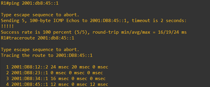
The traceroute shows the path: R1 → R2 → R3 → R4
Routing Loop Investigation
Remove all static routes and configure clockwise default routes only:
R1
1
2
3
4
no ipv6 route 2001:db8:23::/64 2001:db8:12::2
no ipv6 route 2001:db8:34::/64 2001:db8:12::2
no ipv6 route 2001:db8:45::/64 2001:db8:12::2
ipv6 route ::/0 2001:db8:12::2
R2
1
ipv6 route ::/0 2001:db8:23::1
R3
1
ipv6 route ::/0 2001:db8:34::1
R4
1
ipv6 route ::/0 2001:db8:45::1
R5
1
ipv6 route ::/0 2001:db8:51::1
Test with a non-existent address:
1
R1# traceroute 2001:2b8:77::1
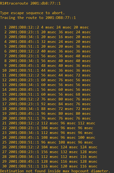
Result: The packet loops infinitely through the ring (R1 → R2 → R3 → R4 → R5 → R1) until the Hop Limit reaches 0.
Analysis:
- Each router forwards unknown destinations clockwise
- No router knows the actual destination
- The packet circles the ring until Hop Limit expires
- ICMPv6 “Hop Limit Exceeded” message is returned
Part 2: IPv4 Configuration
IPv4 Addressing Plan
| Link | Network | Router A | Router B |
|---|---|---|---|
| R1-R2 | 192.168.12.0/24 | .1 (R1 S0/0) | .2 (R2 S0/0) |
| R2-R3 | 192.168.23.0/24 | .2 (R2 S0/1) | .1 (R3 S0/0) |
| R3-R4 | 192.168.34.0/24 | .2 (R3 S0/1) | .1 (R4 S0/0) |
| R4-R5 | 192.168.45.0/24 | .2 (R4 S0/1) | .1 (R5 S0/0) |
| R5-R1 | 192.168.51.0/24 | .2 (R5 S0/1) | .1 (R1 S0/1) |
Note: This lab uses /24 subnets for simplicity. In production networks, use /30 (4 addresses, 2 usable) or /31 (2 addresses) for point-to-point links to conserve IPv4 address space.
Configuration Commands
R1 Serial0/0
1
2
3
4
interface Serial0/0
 encapsulation ppp
 ip address 192.168.12.1 255.255.255.0
 no shutdown
R1 Serial0/1
1
2
3
4
interface Serial0/1
 encapsulation ppp
 ip address 192.168.51.1 255.255.255.0
 no shutdown
Configure all other router interfaces following the addressing plan.
Static Routes Configuration
R1
1
2
3
ip route 192.168.23.0 255.255.255.0 192.168.12.2
ip route 192.168.34.0 255.255.255.0 192.168.12.2
ip route 192.168.45.0 255.255.255.0 192.168.12.2
Configure similar static routes on all routers.
Test Connectivity
1
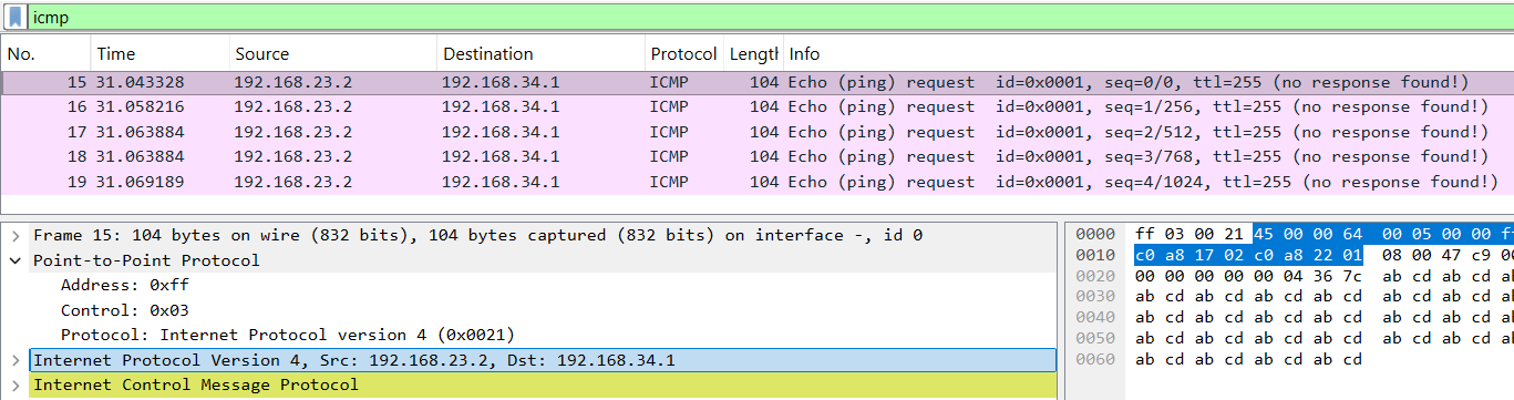
R2# ping 192.168.34.1
Wireshark shows PPP frames carrying ICMP packets with decrementing TTL values.
IPv4 Routing Loop Test
Replace static routes with default routes (clockwise only):
R1
1
ip route 0.0.0.0 0.0.0.0 192.168.12.2
Apply similar default routes on all routers.
Test with non-existent address:
1
R1# traceroute 192.168.77.1
Result:
- Packet loops through the ring
- TTL decrements: 255 → 250 → 245 → … → 0
- ICMP “Time Exceeded” message returned
- Identical behavior to IPv6 routing loop
Key Takeaways
PPP Encapsulation: Standard protocol for serial WAN links, provides Layer 2 connectivity.
Static Routing: Required for routers to reach non-adjacent networks in the topology.
Route Types:
- Connected (C): Directly attached networks
- Local (L): Router’s own interface addresses
- Static (S): Manually configured routes
Routing Loops: Default routes in ring topologies cause infinite forwarding loops for unknown destinations.
Loop Prevention:
- IPv6: Hop Limit field decrements at each router
- IPv4: TTL (Time To Live) field decrements at each router
- Packet dropped when counter reaches 0
Protocol Behavior: IPv4 and IPv6 routing behave identically in this topology.
Lab Files
Download Full Lab Report (PDF - French)
Configuration Files:
Lab Environment: GNS3, Cisco 3725 routers with WIC-2T cards, IOS c3725-adventerprisek9-mz.124-15.T14