VLAN Trunk Ports and Router-on-a-Stick
Lab Instructions
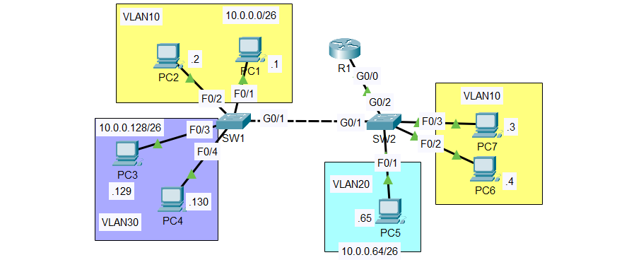
Configure the switch interfaces connected to PCs as access ports in the correct VLAN.
Configure the connection between SW1 and SW2 as a trunk, allowing only the necessary VLANs. Configure an unused VLAN as the native VLAN. Make sure all necessary VLANs exist on each switch.
Configure the connection between SW2 and R1 using Router-on-a-Stick. Assign the last usable address of each subnet to R1’s subinterfaces.
Test connectivity by pinging between PCs. All PCs should be able to reach each other.
The lab was designed in Cisco Packet Tracer.
Note: This lab is from Jeremy’s IT Lab - VLANs (Part 2) - Day 17 Lab, CCNA 200-301 Complete Course.
IP Addressing Scheme
| VLAN | Name | Network | First Host | Last Host | Gateway |
|---|---|---|---|---|---|
| 10 | VLAN10 | 10.0.0.0/26 | 10.0.0.1 | 10.0.0.61 | 10.0.0.62 |
| 20 | VLAN20 | 10.0.0.64/26 | 10.0.0.65 | 10.0.0.125 | 10.0.0.126 |
| 30 | VLAN30 | 10.0.0.128/26 | 10.0.0.129 | 10.0.0.189 | 10.0.0.190 |
| 999 | Native | - | - | - | (Unused VLAN) |
Configuration Commands
Step 1: Configure VLANs on Both Switches
SW1
1
2
3
4
5
6
7
8
9
10
11
vlan 10
 name VLAN10
 exit

vlan 20
 name VLAN20
 exit

vlan 30
 name VLAN30
 exit
SW2
1
2
3
4
5
6
7
8
9
10
11
vlan 10
 name VLAN10
 exit

vlan 20
 name VLAN20
 exit

vlan 30
 name VLAN30
 exit
Step 2: Configure Access Ports
SW1 - Access Ports
VLAN 10:
1
2
3
interface range FastEthernet0/1-2
 switchport mode access
 switchport access vlan 10
VLAN 30:
1
2
3
interface range FastEthernet0/3-4
 switchport mode access
 switchport access vlan 30
SW2 - Access Ports
VLAN 10:
1
2
3
interface range FastEthernet0/2-3
 switchport mode access
 switchport access vlan 10
VLAN 20:
1
2
3
interface FastEthernet0/1
 switchport mode access
 switchport access vlan 20
Step 3: Configure Trunk Ports
SW1 to SW2 Trunk
1
2
3
4
5
interface GigabitEthernet0/1
 switchport mode trunk
 switchport trunk allowed vlan 10,30
 switchport trunk native vlan 999
 no shutdown
switchport trunk encapsulation dot1q
On this swicth there’s only dot1q encapsulation, so no need to enter the command ` switchport trunk encapsulation dot1q`
SW2 to SW1 Trunk
1
2
3
4
5
interface GigabitEthernet0/1
 switchport mode trunk
 switchport trunk allowed vlan 10,30
 switchport trunk native vlan 999
 no shutdown
SW2 to R1 Trunk
1
2
3
4
5
6
interface GigabitEthernet0/2
 switchport trunk encapsulation dot1q
 switchport mode trunk
 switchport trunk allowed vlan 10,20,30
 switchport trunk native vlan 999
 no shutdown
Step 4: Configure Router-on-a-Stick
R1
1
2
3
4
5
6
7
8
9
10
11
12
13
14
15
16
17
interface GigabitEthernet0/0
 no shutdown

interface GigabitEthernet0/0.10
 encapsulation dot1Q 10
 ip address 10.0.0.62 255.255.255.192
 description Gateway for VLAN10

interface GigabitEthernet0/0.20
 encapsulation dot1Q 20
 ip address 10.0.0.126 255.255.255.192
 description Gateway for VLAN20

interface GigabitEthernet0/0.30
 encapsulation dot1Q 30
 ip address 10.0.0.190 255.255.255.192
 description Gateway for VLAN30
Step 5: Configure PCs
VLAN 10:
- PC1: 10.0.0.1/26, Gateway: 10.0.0.62
- PC7: 10.0.0.3/26, Gateway: 10.0.0.62
- PC2: 10.0.0.2/26, Gateway: 10.0.0.62
VLAN 20:
- PC5: 10.0.0.65/26, Gateway: 10.0.0.126
VLAN 30:
- PC3: 10.0.0.129/26, Gateway: 10.0.0.190
- PC4: 10.0.0.130/26, Gateway: 10.0.0.190
- PC6: 10.0.0.4/26, Gateway: 10.0.0.190
Verification
VLAN Configuration
SW1 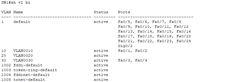
SW2 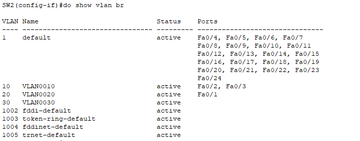
Trunk Configuration
SW1 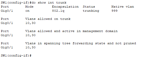 SW2
SW2 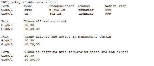
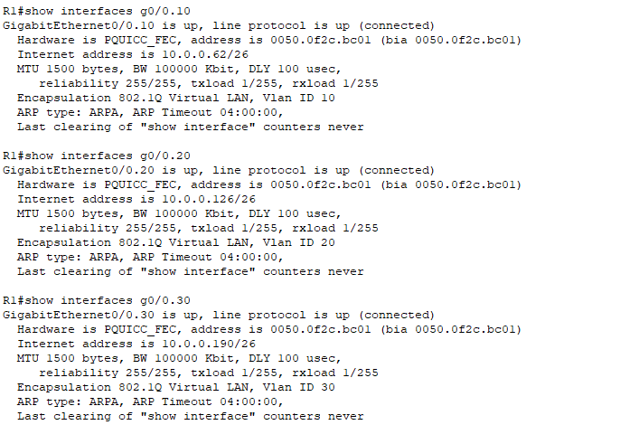
Router Subinterfaces
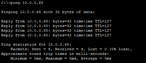
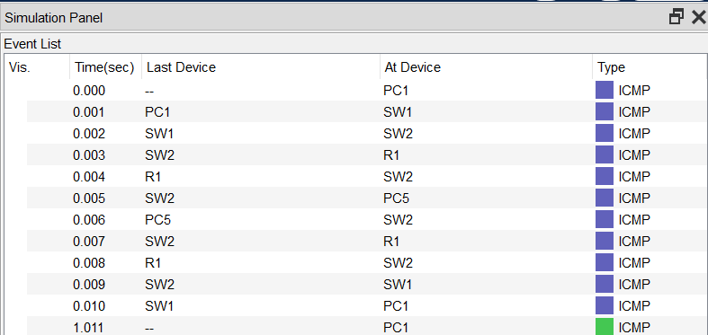
Connectivity Test
PC1 (VLAN10) to PC5 (VLAN20):