Subnetting VLSM
Lab Instructions
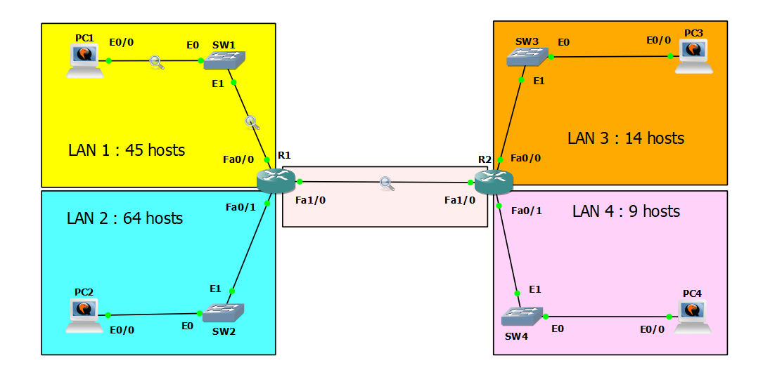
Subnet the 192.168.5.0/24 network to provide sufficient addressing for each LAN and the point-to-point connection between R1 and R2.
Assign the first usable address to the PC in each LAN.
Assign the last usable address to the router’s interface in each LAN.
Configure static routes on each router so that all PCs can ping each other.
Configure a 5-router ring topology with PPP serial links, implement IPv4/IPv6 static routing, and analyze routing loop behavior.
The lab was designed in GNS3, using Debian Buster and Cisco 3725 routers.
Note: This lab is inspired by Jeremy’s IT Lab - Subnetting (VLSM) - Day 15 Lab, and was completed using Cisco Packet Tracer.
Subnetting Planning
Since the given subnet mask is /24 in CIDR notation, we can use this subnetting table:
| Subnet Mask | /24 | /25 | /26 | /27 | /28 | /29 | /30 | /31 | /32 |
|---|---|---|---|---|---|---|---|---|---|
| Subnets | 1 | 2 | 4 | 8 | 16 | 32 | 64 | 128 | 256 |
| Hosts | 256 | 128 | 64 | 32 | 16 | 8 | 4 | 2 | 1 |
Essential Formulas
1
2
3
4
5
6
Borrowed bits = Current CIDR - Default CIDR
Number of subnets = 2^(borrowed bits)
Host bits = 32 - CIDR
Total addresses = 2^(host bits)
Usable hosts = 2^(host bits) - 2
Block size = 256 - (subnet mask octet value)
For example, with /27, the original Class C prefix is /24, so 27 - 24 = 3 borrowed bits, giving us 2^3 = 8 subnets.
The number of host bits is 32 - 27 = 5, so we have 2^5 = 32 total addresses, with 30 usable hosts (32 - 2 for network and broadcast addresses).
I arranged the networks from largest to smallest:
- LAN 2 - 64 hosts
- LAN 1 - 45 hosts
- LAN 3 - 14 hosts
- LAN 4 - 9 hosts
- Point-to-Point Link (R1 to R2) - 2 hosts
For LAN 2
The minimum subnet that can accommodate 64 hosts is 128 hosts (not 64, because the network and broadcast addresses are not usable for PCs). So I need the subnet mask /25.
Given Range: 192.168.5.0/24
| Network ID | Subnet Mask | Hosts | Network |
|---|---|---|---|
| 192.168.5.0 | /25 | 128 | LAN 2 |
| 192.168.5.128 | /25 | 128 | Unused |
For LAN 1
The minimum subnet that can accommodate 45 hosts is 64 hosts with subnet mask /26.
Available Range: 192.168.5.128/25
| Network ID | Subnet Mask | Hosts | Network |
|---|---|---|---|
| 192.168.5.128 | /26 | 64 | LAN 1 |
| 192.168.5.192 | /26 | 64 | Unused |
For LAN 3
The minimum subnet that can accommodate 14 hosts is 16 hosts (minus 2 for network and broadcast addresses) with subnet mask /28.
Available Range: 192.168.5.192/26
| Network ID | Subnet Mask | Hosts | Network |
|---|---|---|---|
| 192.168.5.192 | /28 | 16 | LAN 3 |
| 192.168.5.208 | /28 | 16 | Unused |
For LAN 4
The minimum subnet that can accommodate 9 hosts is 16 hosts with subnet mask /28.
Available Range: 192.168.5.208/28
| Network ID | Subnet Mask | Hosts | Network |
|---|---|---|---|
| 192.168.5.208 | /28 | 16 | LAN 4 |
| 192.168.5.224 | /28 | 16 | Unused |
For Point-to-Point Link
For a point-to-point link between two routers, we need only 2 addresses. We use /30 which provides 4 addresses (2 usable).
Available Range: 192.168.5.224/28
| Network ID | Subnet Mask | Hosts | Network |
|---|---|---|---|
| 192.168.5.224 | /30 | 4 | Point-to-Point |
Configuration Commands
LAN 2
PC2
1
2
3
4
5
6
7
8
9
10
11
nano /etc/network/interfaces

# Add the following lines:
auto ens3
iface ens3 inet static
  address 192.168.5.1
  netmask 255.255.255.128
  gateway 192.168.5.126

# Restart networking
systemctl restart networking
R1 interface Fa0/1
1
2
3
interface FastEthernet0/1
 ip address 192.168.5.126 255.255.255.128
 no shutdown
LAN 1
PC1
1
2
3
4
5
6
7
8
9
10
11
nano /etc/network/interfaces

# Add the following lines:
auto ens3
iface ens3 inet static
  address 192.168.5.129
  netmask 255.255.255.192
  gateway 192.168.5.190

# Restart networking
systemctl restart networking
R1 interface Fa0/0
1
2
3
interface FastEthernet0/0
 ip address 192.168.5.190 255.255.255.192
 no shutdown
LAN 3
PC3
1
2
3
4
5
6
7
8
9
10
11
nano /etc/network/interfaces

# Add the following lines:
auto ens3
iface ens3 inet static
  address 192.168.5.193
  netmask 255.255.255.240
  gateway 192.168.5.206

# Restart networking
systemctl restart networking
R2 interface Fa0/0
1
2
3
interface FastEthernet0/0
 ip address 192.168.5.206 255.255.255.240
 no shutdown
LAN 4
PC4
1
2
3
4
5
6
7
8
9
10
11
nano /etc/network/interfaces

# Add the following lines:
auto ens3
iface ens3 inet static
  address 192.168.5.209
  netmask 255.255.255.240
  gateway 192.168.5.222

# Restart networking
systemctl restart networking
R2 interface Fa0/1
1
2
3
interface FastEthernet0/1
 ip address 192.168.5.222 255.255.255.240
 no shutdown
Point-to-Point Link
R1 interface Fa1/0
1
2
3
interface FastEthernet1/0
 ip address 192.168.5.225 255.255.255.252
 no shutdown
R2 interface Fa1/0
1
2
3
interface FastEthernet1/0
 ip address 192.168.5.226 255.255.255.252
 no shutdown
Static Routes Configuration
R1
1
2
ip route 192.168.5.192 255.255.255.240 192.168.5.226
ip route 192.168.5.208 255.255.255.240 192.168.5.226
R2
1
2
ip route 192.168.5.0 255.255.255.128 192.168.5.225
ip route 192.168.5.128 255.255.255.192 192.168.5.225
Verification
After configuring all interfaces, static routes, and enabling switch interfaces, verify connectivity:
1
2
3
4
5
6
7
8
9
# From PC1
ping 192.168.5.1    # PC2
ping 192.168.5.193  # PC3
ping 192.168.5.209  # PC4

# From PC2
ping 192.168.5.129  # PC1
ping 192.168.5.193  # PC3
ping 192.168.5.209  # PC4
Test Case 1: PC1 to PC2 (Same Router)
Ping test:
1
2
3
4
5
6
7
8
9
10
root@buster00:~# ping -c 4 -t 2 192.168.5.1
PING 192.168.5.1 (192.168.5.1) 56(84) bytes of data.
64 bytes from 192.168.5.1: icmp_seq=1 ttl=63 time=29.6 ms
64 bytes from 192.168.5.1: icmp_seq=2 ttl=63 time=22.4 ms
64 bytes from 192.168.5.1: icmp_seq=3 ttl=63 time=36.5 ms
64 bytes from 192.168.5.1: icmp_seq=4 ttl=63 time=23.3 ms

--- 192.168.5.1 ping statistics ---
4 packets transmitted, 4 received, 0% packet loss, time 13ms
rtt min/avg/max/mdev = 22.410/27.950/36.476/5.641 ms
Traceroute:
1
2
3
4
root@buster00:~# traceroute -q 1 -w 1 192.168.5.1
traceroute to 192.168.5.1 (192.168.5.1), 30 hops max, 60 byte packets
 1  192.168.5.190 (192.168.5.190)  12.540 ms
 2  192.168.5.1 (192.168.5.1)  24.632 ms
Analysis:
- TTL = 63: The reply packet passed through 1 router (R1). Linux default TTL is 64, decremented by 1.
- Path: PC1 (LAN 1) → R1 Fa0/0 → R1 Fa0/1 → PC2 (LAN 2)
- Hops: 2 hops total (gateway + destination)
- Round-trip time: Average ~28 ms
Note: The -t 2 option sets the outgoing TTL to 2, but the displayed TTL (63) is from the reply packet sent by PC2 with its default TTL of 64.
Test Case 2: PC1 to PC4 (Multiple Routers)
Ping test with insufficient TTL:
1
2
3
4
5
6
7
8
9
root@buster00:~# ping -c 4 -t 2 192.168.5.209
PING 192.168.5.209 (192.168.5.209) 56(84) bytes of data.
From 192.168.5.226 icmp_seq=1 Time to live exceeded
From 192.168.5.226 icmp_seq=2 Time to live exceeded
From 192.168.5.226 icmp_seq=3 Time to live exceeded
From 192.168.5.226 icmp_seq=4 Time to live exceeded

--- 192.168.5.209 ping statistics ---
4 packets transmitted, 0 received, +4 errors, 100% packet loss, time 13ms
Ping test with sufficient TTL:
1
2
3
4
5
6
7
8
9
10
root@buster00:~# ping -c 4 -t 3 192.168.5.209
PING 192.168.5.209 (192.168.5.209) 56(84) bytes of data.
64 bytes from 192.168.5.209: icmp_seq=1 ttl=62 time=62.7 ms
64 bytes from 192.168.5.209: icmp_seq=2 ttl=62 time=57.2 ms
64 bytes from 192.168.5.209: icmp_seq=3 ttl=62 time=61.6 ms
64 bytes from 192.168.5.209: icmp_seq=4 ttl=62 time=51.10 ms

--- 192.168.5.209 ping statistics ---
4 packets transmitted, 4 received, 0% packet loss, time 11ms
rtt min/avg/max/mdev = 51.982/58.364/62.707/4.224 ms
Traceroute:
1
2
3
4
5
root@buster00:~# traceroute -q 1 -w 1 192.168.5.209
traceroute to 192.168.5.209 (192.168.5.209), 30 hops max, 60 byte packets
 1  192.168.5.190 (192.168.5.190)  8.894 ms
 2  192.168.5.226 (192.168.5.226)  38.298 ms
 3  192.168.5.209 (192.168.5.209)  52.686 ms
Analysis:
- TTL = 62: The reply packet passed through 2 routers (R1 and R2). Default TTL is 64, decremented twice.
- Path: PC1 (LAN 1) → R1 Fa0/0 → R1 Fa1/0 → R2 Fa1/0 → R2 Fa0/1 → PC4 (LAN 4)
- Hops: 3 hops total (R1 → R2 → destination)
- Round-trip time: Average ~58 ms (higher than PC1→PC2 due to additional router hop)
TTL demonstration:
- With TTL=2: Packet dies at R2 (192.168.5.226) after 2 hops, returning “Time to live exceeded”
- With TTL=3: Packet successfully reaches PC4, demonstrating that exactly 3 hops are needed
This confirms that the static routes are correctly configured and both routers are properly forwarding traffic between all networks.