VLAN Access Mode
Lab Instructions
Configure the correct IP address/subnet mask on each PC. Set the gateway address as the LAST USABLE address of the subnet.
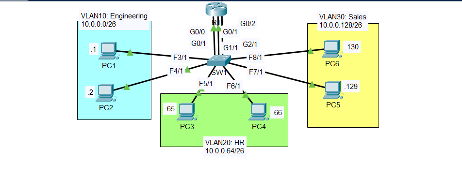
Make three connections between R1 and SW1. Configure one interface on R1 for each VLAN. Make sure the IP addresses are the gateway address you configured on the PCs.
Configure SW1’s interfaces in the proper VLANs. Remember the interfaces that connect to R1! Name the VLANs (Engineering, HR, Sales).
Ping between the PCs to check connectivity. Send a broadcast ping from a PC (ping the subnet broadcast address), and see which PCs devices receive the broadcast (use Packet Tracer’s Simulation Mode).
The lab was designed in Cisco Packet Tracer.
Note: This lab is from Jeremy’s IT Lab - VLANs (Part 1) - Day 16 Lab, CCNA 200-301 Complete Course.
IP Addressing Scheme
| VLAN | Name | Network | First Host | Last Host | Gateway (Last Usable) |
|---|---|---|---|---|---|
| 10 | Engineering | 10.0.0.0/26 | 10.0.0.1 | 10.0.0.61 | 10.0.0.62 |
| 20 | HR | 10.0.0.64/26 | 10.0.0.65 | 10.0.0.125 | 10.0.0.126 |
| 30 | Sales | 10.0.0.128/26 | 10.0.0.129 | 10.0.0.189 | 10.0.0.190 |
Broadcast Addresses:
- VLAN 10: 10.0.0.63
- VLAN 20: 10.0.0.127
- VLAN 30: 10.0.0.191
Configuration Commands
Step 1: Configure PCs
VLAN 10 - Engineering
PC1:
1
2
3
IP Address: 10.0.0.1
Subnet Mask: 255.255.255.192
Default Gateway: 10.0.0.62
PC2:
1
2
3
IP Address: 10.0.0.2
Subnet Mask: 255.255.255.192
Default Gateway: 10.0.0.62
VLAN 20 - HR
PC3:
1
2
3
IP Address: 10.0.0.65
Subnet Mask: 255.255.255.192
Default Gateway: 10.0.0.126
PC4:
1
2
3
IP Address: 10.0.0.66
Subnet Mask: 255.255.255.192
Default Gateway: 10.0.0.126
VLAN 30 - Sales
PC5:
1
2
3
IP Address: 10.0.0.129
Subnet Mask: 255.255.255.192
Default Gateway: 10.0.0.190
PC6:
1
2
3
IP Address: 10.0.0.130
Subnet Mask: 255.255.255.192
Default Gateway: 10.0.0.190
Step 2: Configure Router Interfaces
R1
1
2
3
4
5
6
7
8
9
10
11
interface GigabitEthernet0/0
 ip address 10.0.0.62 255.255.255.192
 no shutdown

interface GigabitEthernet0/1
 ip address 10.0.0.126 255.255.255.192
 no shutdown

interface GigabitEthernet0/2
 ip address 10.0.0.190 255.255.255.192
 no shutdown
Step 3: Configure VLANs on SW1
Create VLANs
1
2
3
4
5
6
7
8
9
10
11
vlan 10
 name Engineering
 exit

vlan 20
 name HR
 exit

vlan 30
 name Sales
 exit
Assign Ports to VLANs
VLAN 10 - Engineering:
1
2
3
4
int range g0/1, fa3/1, fa4/1
 switchport mode access
 switchport access vlan 10
 no shutdown
VLAN 20 - HR:
1
2
3
int range g1/1, fa5/1, fa6/1
 switchport mode access
 switchport access vlan 20
VLAN 30 - Sales:
1
2
3
int range g2/1, fa7/1, fa8/1
 switchport mode access
 switchport access vlan 30
Verification
VLAN Configuration
1
2
3
4
5
6
7
8
9
10
11
12
13
SW1#show vlan br

VLAN Name                             Status    Ports
---- -------------------------------- --------- -------------------------------
1    default                          active    Fa9/1
10   Engineering                      active    Gig0/1, Fa3/1, Fa4/1
20   HR                               active    Gig1/1, Fa5/1, Fa6/1
30   Sales                            active    Gig2/1, Fa7/1, Fa8/1
1002 fddi-default                     active
1003 token-ring-default               active
1004 fddinet-default                  active
1005 trnet-default                    active
SW1#
Router Interfaces
1
2
3
4
5
6
R1#show ip int br
Interface              IP-Address      OK? Method Status                Protocol
GigabitEthernet0/0     10.0.0.62       YES manual up                    up
GigabitEthernet0/1     10.0.0.126      YES manual up                    up
GigabitEthernet0/2     10.0.0.190      YES manual up                    up
Vlan1                  unassigned      YES unset  administratively down down
Step 4: Connectivity Tests
Test 1: Ping Across VLANs
From PC1 (VLAN 10) to PC3 (VLAN 20):
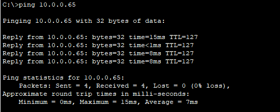
Packet Tracer Simulation Mode:
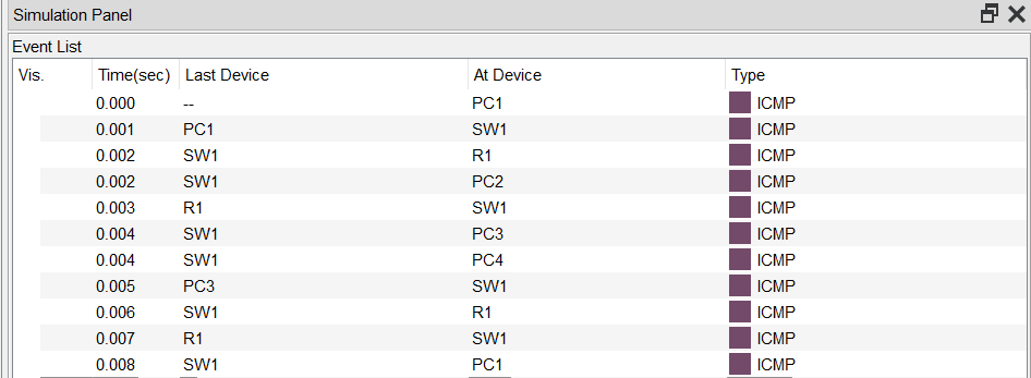
Test 2: Broadcast Ping
From PC1, ping the VLAN 10 broadcast address (10.0.0.63):
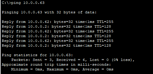
Packet Tracer Simulation Mode:
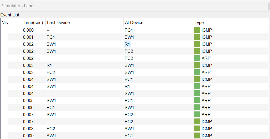
Key Observations:
- Broadcast only reaches devices in VLAN 10 (PC1, PC2, R1 G0/0)
- Devices in VLAN 20 and VLAN 30 do NOT receive the broadcast
Key Concepts
VLANs (Virtual LANs): VLANs logically segment a network at Layer 2. Devices in different VLANs cannot communicate without a Layer 3 device.
Broadcast Domain: Each VLAN creates a separate broadcast domain. Broadcasts are only forwarded within the same VLAN.
Inter-VLAN Routing: This lab uses separate physical router interfaces for each VLAN. Each router interface acts as the gateway for its VLAN.
Gateway Address: The last usable IP address in each subnet is configured as the gateway, following common network design practices.